Menu

Show posts

This section allows you to view all posts made by this member. Note that you can only see posts made in areas you currently have access to.

Show posts Menu

Messages - wayne petty

#3526
Quote from: "Dr Flowgood"Purple pickup,   ////  Its interesting stuff, the gas stations owned by oil companys sure dont have any interest in selling ethanol. I dont think e85 will ever be a big hit, Ive read that we cant grow enough corn to make enough of it to replace all the gas we use and we need it as a food more than a fuel.

PS: what are these big fuel injectors used in, are they throttle body injectors?
Doug

the huge fuel injectors are on 80's up  ford 3.8 CFI (36lbs/green top) and 5.0 CFI(59 lbs dark blue top)  and 5.0HO CFI (62 lbs grey top)  i found a site by googling ford cfi injectors that had a complete list of bosch and ford numbers to flow rates and voltages. i printed the whole thing.  then cleaned my desk.  they have a spool that adapts the cfi special top to a conventional oring top .

i did find this link with lots of cool stuff wholesale stuff.      i used to have an account with these people through one of the shops i worked at... anybody who rebuilds carbs or messes with fuel injection for a living should download the various pages they have. they have stuff that nobody else has. because they make it... and they sell it to every carb shop.  the carb kits in the 6"x6"x1.5" boxes are theirs in various outer boxes.

http://walkerproducts.com/downloads/catalogs/2006HighPerformanceCatalog.pdf


http://walkerproducts.com
#3527
Rodder's Roundtable / brake light switches
September 04, 2007, 02:48:56 AM
here is a link to cole hersee.      look for the switches link then the stoplamp switches  and a bunch of links open.. there is a pull down box at the top to narrow the selection

click on the spects link to open each one... pressures are also listed

http://www.colehersee.com/catalog_top/index.htm

these area available at most truck lighting stores and probably through a cross reference through a normal autoparts store.


i hope this helps...
#3528
Rodder's Roundtable / Re: removing smog accesories
September 02, 2007, 03:42:58 PM
Quote from: "zzebby"Ford 5 liter Was stripping off the misc stuff that won't be needed and see that there are steel lines from the back of the heads going into a valve of some sort that is plumbed to the smog pump.  Are  there exhaust gases coming out the back of the heads ??   Can I cap them off ?   If I can't get a shorter serpentine belt then I'll run the smog pump as is but no lines on it.  Will it last or should I put some oil in  it and cap it off.

thanks

on many ford engines there are threaded holes in both ends of the heads that allow the smog pump to pump air into the exhaust ports to help heat the cats for the first 90 seconds or so.    FYI.. for pepole with fuel injection, the "upstream air" into these manifolds should only be on for the first 90 seconds or less.. if the diverter valve is damaged and leaking it will dilute the exhaust gasses flowing past the O2 sensor. and really screw up the fuel mixture.  down stream air goes into the pipe beyond the first O2 sensor or into the sides of the cat.  this downstream air will not affect fuel mixture.

ok,  these holes are threaded 5/8"-11, there are threaded inserts in the front of the heads that reduce the size to 3/8"-16. some engine builder may have some.. but just use a short cap screw like 5/8"-11 X 1'  aftermarket ones area available or even an allen set screw...

be sure to run a tap into the hole to clean out the carbon... but use a vacuum to clean out the debris... blowing into the hole may cause carbon /metal bits to blow into the exhaust ports... or if you have the exhaust manifold off blow air into the front exhaust port and each one further back in order just to be safe.. they all interconnect...

btw
the 5.0 cobra mustang heads with f3 or f4 casting numbers don't have air injection in them.   no bumps in the exhaust port either...and a slightly smaller chamber to boot.   for the big block ford guys the F3 casting 460 heads  also do not  have the air injection lumps.. looks like a much better exhaust port... for some reason there are footnotes everywhere about using 88 up 460 heads with carb manifolds...i had a set of d3 and f3 castings next to each other and could not see the differnce on the intake side.
#3529
i saw the artical also..

this might be of some help.

http://www.edelbrock.com/automotive_new/mc/carbs_acc/pdf/carb_app_chart.pdf


i have also seen a few multi fuel motors showing up in the junk yards lately...  someone else has gotten the injectors everytime.

a little off subject...but i just found out the blue top ford 5.0L cfi injectors flow 59 lbs per hour. the grey top 5.0 HO cfi injectors flow 62 lbs and the green top  3.8l v6 cfi's flow only 36 lbs.  someone even makes adaptors for the top to install them in normal fuel rails...
#3530
Rodder's Roundtable / External tranny filter
September 02, 2007, 03:21:58 AM
yea i know  wayne again...

in some trannys  the cooler return line lubes the rear case bearing and the sprag. maybe more..   going forward the sprag at least in c4/c6 trannys is overrunning... it is this way in bw35's  since i dont do trannys for a living anymore it's been almost 25 years since i worked every day in a tranny shop i have not kept up with newer stuff lube paths.

i do know that if you really want a tranny to live keep it under 180F , you do that by installing a big remote cooler.. my brother in law, a plumber had 2 sending units on his tranny in his overloaded camper special.  one in the cooler return line and another into the side of the pan. with a switch...
#3531
Quote from: 1FATGMC    

Quote from: "kb426"My two cents worth on wings at Bonneville would be for stabilization. .................

That is why we run a spoiler that we hope is neutral as far as down-force goes.  The spoiler allows us to run the side Spill Plates (vertical fins on the side of the spoiler) that help to keep the car running straight like the tail on a plane.  We have them as large as the rules allow.


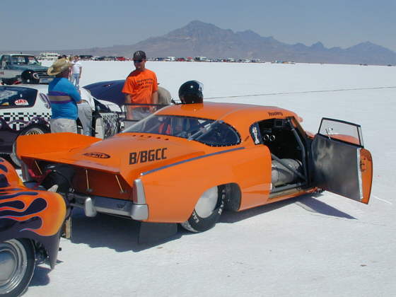
hmmm... that statment brought up an old idea.   a hollow spoiler with an open lip... like a siphon. the upper half is a conventional shape.. the lower half follows the shape of the rear of the deck lid or body down.. inside it is hollow and there are holes drilled into the rear panel so as the car gets to speed the low pressure across the tip of the spoiler sucks the air out of the car body. or if it is ducted properly out from between the belly pan and the bottom of the car...

i thought of this a long time ago when i spent a weekend working the pits on a aa/fc that mike dunn was driving.. my though was to get the air out from under the back of the body where there were only a few holes..  the car owner was not impressed with the extra idea that all of the flames from the engine fires that they had been having would become a flaming peacock type of display routed through the spoiler..  that was the season mike dunn lost the engine, burned the chutes off, burned the rear tires off, burned the body off, and hit the catch nets at 175. then jumpped out of what remained like something big happend..


i would have loved to have spend the rest of the season with them.

the guy next to us with a s/s XX looked like he had a lot of pressure in his slicks...  he did ... like 32 psi.. he said it stopped the back of the  car from swinging on the top end...

wayne...  thinker and entertainer....


ps  did anybody see the artical on the Hindenberg.. seems they painted it with aluminum powder and iron oxide in a nitrocellulose base. guess they never welded railroad track. talk about explosive...
#3532
Rodder's Roundtable / Re: Charging problem
August 28, 2007, 10:16:13 PM
Quote from: phat46I have a Ford that's not charging. A 70ish three wire alt.  It was fine but I took it off to grind a touch off the cooling blades because they were slightly rubbing the frame. I put it back on and now it won't charge. If i rev it the idiot light will fade but then come back bright when the revs come down.


a thought just hit me
did you remove the fan from the shaft???  what did you use to remove the nut and to install it....3/8" allen and a box end wrench or an impact of some type????

if you removed the fan from the front,  the rotor shaft may have slipped back in the bearing while it was apart. the comutator may be grooved or dirty and the brushes may have become damaged or coated with grease....

also did you tighten it with an impact???? that is teh proper way to do it.. just doing it with a wrench  may allow the pulley to slip on the shaft and cause the failure you describe...

60 amp alternators take almost 5 horsepower to turn at max charge... this is why drag racers has a switch to shut off the  alt during a run.

do you know about the thumb belt tention check/ajustment just for alternators with external blades..

the belt needs to be just a little tighter if you can push the alternator blade/pulley around without turning the crankshaft...

WITH THE KEY OFF GUYS....

too tight will cause the waterpump or alternator bearings to fail sooner

i'am all charged up with desire to know what happend.....
#3533
Rodder's Roundtable / Re: Power Steering Pumps
August 26, 2007, 01:56:30 PM
Quote from: "brti"Ok gearheads,,, can you use a conventional power steering pump on a rack and pinion steering system? :roll: Is there a preasure issue?


behind the 1 inch nut where the pressure hose threads into there is a spring and a plunger..

the plunger has a hex hollow nut screwed into the small end. i seem to recall you can change the amount of washers behind that nut to change the standard operating pressure.

that fitting also has a tiny screen to filter some debris that sometime become clogged be sure to check this.

and the 1 inch nuts can be had in several differnt tube sizes and styles in both inch and metric thread sizes.

inverted flair,  and O ring sealed are some.

btw if anyone experiances trouble changing  the pressure hose a few tips from wayne...


always use a backup wrench..   it is 1' and the same size at the quadrajet filter nuts.  so everybody has one  of those thin 1 inch stampped out of steel fuel filter wrenches..


if you dont and are changing the presure line cut the line off 3/4" to 1" past the tube nut (hacksaw or diagnols) and use a 6 point deep socket. sizes could be 5/8, 15mm, 16mm. 18mm,  

oh yea.  you can now get the 1 inch compbo wrench over the big nut to hold it while loosening the tube nut.    

last tip for all inverted flair fittings and other tight fittings.    break the tube nuts loose by tightening the tube nut first..  this really works and usually prevents rounding off the tube nut...   oh yea.    crow foot line wrenches... cheep from harbor freight..(keyword crowfoot). under 10 bucks

i put them on long extentions and loosen the pressure hoses on conventional steering boxes.  rembember tighten first just a little bit.  

i loaned one to a friend and reminded him to tighten it first... he did not understand the concept...  JUST ENOUGH TO MOVE IT. and handed my back by crow foot in 2 pieces... it was my fault..  i sent him off with my tranny stick and an 24" 1/2" drive breaker bar.  
(tranny stick  36" or longer extention 3/8 drive on the male end, 1/2" drive on the female end, used to remove the most hard to reach bellhousing bolts with a impact type universal socket on the tip...)


wayne ..
#3534
Rodder's Roundtable / Re: Morris Minor progress
August 26, 2007, 01:47:32 AM
Quote from: "Crosley"latest progress on the ol car...

I had my Jegs chassis frame  tube and rear kick up tubes   in the car (no pics)  and they are not going to work. I need to build my own back section to fit the Morris.

I need to fit a drag race  4 link suspension in the back. I'd like to stand the car on it's bumper at the strip.


8)


what if .  the 4 link arms are only a foot long and the rear crossmember  is not straight.   but like this     ----|_____|----   top view
                                              T   |     |   T
                                              I   |      |   I
                                              R----D-----R
                                              E              E

so the rear crossmember kicks back between the tires and the 4 link rods are really short.   more kick back than i have texed


either that or put a drive shaft loop around the tailhousing of the tranny in the middle of a crossmember and hang nascar style swing arms off of that. the top and bottom of the loops should unbolt from 4 bolt flanges so one could pull the tranny from the top or bottom
#3535
Rodder's Roundtable / Re: Charging problem
August 25, 2007, 11:35:34 PM
Quote from: "phat46"I have a Ford that's not charging. A 70ish three wire alt.  It was fine but I took it off to grind a touch off the cooling blades because they were slightly rubbing the frame. I put it back on and now it won't charge. If i rev it the idiot light will fade but then come back bright when the revs come down. All the connections are back where they came off of and they're tight, at both ends. Do these need to be polerized? I don't think they do, but if i really knew I wouldn't be posting here would I???  :lol:


wires on the back of ford alternators are

Bat.  this as stated goes between the back of the alternator and usually the battery side of the starter relay/solenoid

fld   this is the field wire. it goes throough the brushes and powers up the rotating rotor.    the wire comes from the F term on the regualtor.  and is pulsed by the regulator to change the output of the alternator.   by disconecting the regualtor and on fords jumping from A to the F  on the regulator pigtale you can tell if the alternaotr is working as it should almost instantly go over 15 volts... do not do this for more than a few seconds..

STA    this is the stator terminal.   it will have half the output voltage of the alternator when the alternator is charging. """only when the alternator is charging."""" this terminal hooks to the S term on the voltage regulaotr and let the regulator know what or how fast the alt is turning..   it used to make a mechanical contact viberate. but there are probably not that many mechanical regulators left.    you can test this with a volt meter set at 20 volts A/C  with the alternator charging or during full field test...

there may also be a ground wire on some applications. to ground the regualtor to the case of the alternator.  this prevents overcharging and under charging do to voltage drops through the system.  see volt drops below

if any of the wires is broken and they do break the alternator will not work. use the continuity beep on your digital volt meter to test them with the car battery disconected...

(digital volt meters can be had for under 5 bucks all over the place...)


charging system specs

charging systems must be tested with the battery at full charge...

batterys are tested with everything turned off and the engine off.
turn the head lights for one minute then off. this removes the surface charge.

now with the volt meter set to 20 volts D/C  

12.65 volts is 100% charge
12.45 volts is 50%  charge
12.25 volts is 25% charge

you cannot get an accurate reading with an analog meter. that is for testing

once you start the car and the battery and hte battery has tested close to 100% charge

the output voltage should be

14.1 to 14.5 volts d/c

if it is under check for loose belts. or bad alternators.

what ever you do never never never pull the battery cable off to test the alternator..
the battery loads the alternator and keeps the output voltage from going out of control.. the diodes in most are  25 amp 100 volts PIV (peak inverse voltage) the alternator going without a battery can get to the voltage for a millasecond and blow out or weaken the diodes.  it may fail at a later time... kinda like revving the motor in park to see if the valves are going to float. over stesses componants....

jump starting a car with a dead battery does the same thing.  puts a huge load on the alternator. then the other car trys to crank.. the alternaotr trys to put out that amperage... overheats / overstresses the diodes.

proper way is to charge the dead car for 10 minutes. then turn off your motor leaving the cables attached.  and the car will start.

you can only damage the alternator with the engine off if you hook the cables up backwards... the fuseable link goes if you have one... if you dont then the diodes...

should i continue...?????


does everybody know what a voltage drop test is..???

volt meters test the differnce in voltage between where you test...

#1:  across the battery you will see 12 to 14 volts dc..

#2:   battery  (-) neg term to engine block with the engine running.. less than .02 volts d/c  over that look for a bad ground wire

#3:   Battery  (-) to the body or frame. engine running all the head lights on..   less than .02 volts D/C


#4    battery (+) positive term to the alternator output. this may be a little higher like .08 volts D/C


if you see any thing over 1 volt you have a serious problem... like a loose connector, bad krimp, freyed wire, corrosion in the mechanical connection..

wire brush the faces of the terminals if they are dirty at all...

lead and the zinc coating oxidizes and becomes lead oxide or zinc oxide. both are ceramic and insulate.  thats why the crust on the battery posts is crunchy.


do feel free to edit this if i have posted something wrong..


wayne...
#3536
Rodder's Roundtable / rear end options
August 24, 2007, 09:17:29 PM
ok more things out of my fertile mind.. must be all the fertilizer

rear ends...
one of the help your self junk yards on alameda st just north of manchester ave has got 5 or 6, 80' up jags just sitting there.  just a few parts removed... but i am thinking fords irs like out of a irs mustang cobra.  

a few thoughts on that though.   89 up Tbirds, mark VIII lincolns also use a simular setup.  i was reading about the later model conventional axle 8.8" rear ends with the 31 spline axles instead of the 28 spline units,  if one could swap the 31 spline diff into the 28 spline housing. the mustang unit bolts onto the factory leaf spring mounts which makes it interesting to me. and it has outboard brakes.  my family ended up with a bunch of rovers 2000 tc,sc, 3500s, ser 2a 109, ser 3 88 santana, so i am familiar with inboard brakes..........

the last thing i was wondering about was the corvette rear tranaxle.  looks like the new style TH- 6 bolt tailhousing is the same bolt pattern as the front of the transaxle. so by removing the extension one could have a transaxle set up for mid engine cars or rear engine streamliners.. if you used a manual tranaxle and bolted it to the back of 4L60 4L80 hmm...  that just does not sound right. but....


wayne  thinker of fertilizer
#3537
Rodder's Roundtable / Re: Bondo comparison
August 23, 2007, 09:16:16 PM
the cadillac restoration shop i used to work in only used usc all metal.  but that was the bosses orders. they only did 1950 to 1962 cads. some with 12 foot long quarter panels.

has anybody tryed this? dynatron/bondo #660 i glue everything with it.   i even reinforce motormounts  that are oe with holes in them.   like the 3.0 taurus tranny mount. and all honda mounts on hot hondas.
#3538
i have been thinking about how to measure downforce / loading of the rear tires on the back of race cars for a while.(without a windtunnel). i read and saw the videos of the spins up on the salt and remember seeing all the nextel cup cars loosing the rear and swapping ends.

my ideas. optional and open for debate or whatever.

using bimbo double acting cylinders in a master / slave set up piggybacked to the rear shock mounts. left and right slave cylinders in cockpit agenst a scaled backplate. so when the car goes down under load the master is compressed at the rear end and the slave is extended or retracted depending on which way it is plumbed. video cameras record both the run and the movement of the slave cylinder motions.    

i have followed a trench plate shoring co. flatbed trailer out here in los angeles and they have a gauge mounted in a tail lamp hole.  yes i was that close. the gauge bumps around but shows how much weight is on the trailer.  i guess it was cheeper to install that then getting nailed for being overweight.  it looked like it was attached to the air suspension on the airbag side of the control valve.

idea #2  uses the gauge on the dash. and a custom short stroke hydraulic cylinder to mount the rear springs to. or the coil overs.
this would not be hard to build.  one could almost use a disc brake caliper cut in half.  cut in half means removing the stationary side of the caliper. or maybe even leaving it whole and inserting a block ( i am thinking of a gm style front brake caliper) to stop the piston from coming totally out if the car goes airborne.

idea #3 uses electronics and sensors from lincoln mark 7 air suspension. i have not researched what voltage in and out these level sensors use.   someone will know...  and i thought i knew everything.

these could be hooked to a data logging system that may be installed on the cars.

i just think a bit more down force might be better. i've never been to the salt. el mirage a few times decades ago.  both my autoshop teachers 78/79 were members of the 200 mph club. roger gates and monte wolfe so i kind of got lead that way.  i used to run a renault daulphene powered sand rail up there as a kid. OCIR was a favorite haunt and i worked for big willie robinson at terminal island raceway back in 83 84.

at ocir in the late 70's i ask a wheel manufacturers  rep if they could cast directional blades in the wheels. he said it was impossible.  i guess he was wrong. hmm  and i ask my brother in law a professional plumber back in the early 80's if lead is so poisioness whey are we using it to soldier pipes?

wayne

also got me thinking some of you remember my last boat trip.  i navigated with a handheld gps.  has anyone installed a gps unit on the dashboard  with a rooftop antenna to accurately  measure groundspeed. and map it out after the run.
#3539
Quote from: "C9"My daughter got a nice little Ranger pickup a few weeks back.
Club cab, 6' bed, etc.

We're noticing a vibration that comes in at 60 mph and smooths out a couple mph faster.

I thought at first it was a bad balancing job on the new tires we just put on, but re-balancing didn't help.

This morning I checked the wheels and tires for runout and they were ok.

Took a look at the driveshaft to see if it had too much runout and to my surprise found a two piece driveshaft.

The intermediate bearing looks to be fairly sloppy and I'd guess they're not supposed to be that way.
(First one I was ever involved with.)
It moves around quite a bit inside what looks like a seal . . . as viewed from the rear.

The vibration is definitely coming from the drive train area, we jacked up the truck and spun it up to 70 mph and could feel the vibration come and go.


hi again guys..

be sure to check the trans output shaft bushing.
if you get more than a tiny bit of up down movement the drive shaft will viberate just like you describe.   one does have to pull the rear housing and drive shaft to properly change the bushing and rear tranny seal if it is an automatic. be sure to pick up a rear housing gasket and speedo seals.    if the yoke is damaged where the bushing rides agenst it will have to be changed.   feel it once you have the drive shaft out. before you order any extra parts. as that will be the most expencive part.


wayne