Menu

Show posts

This section allows you to view all posts made by this member. Note that you can only see posts made in areas you currently have access to.

Show posts Menu

Topics - wayne petty

#1
this   


i have been using this for about 15 years now...

why all 6 tests...

test 1 verifies the alternator is putting out some kind of voltage above battery voltage...

test 2 checks the electrical connection between the Negative battery post and the engine block...

test 3 checks the electrical connection between the Negative battery post and the Body..

test 4 checks the electrical connection between the engine and firewall..

test 5 checks the electrical connection between the Positive battery and the Fuses in the fuse block..

test 6 checks the electrical connection between the alternator output stud and the positive battery post....

why do all this... i can do tests 1 thru 4 in less than a minute on most cars..

test 5 takes a minute or two..

test 6 is impossible on some cars. but easily done on others..

lets go over why...

test 2... ever had a negative battery cable loose on the block... or on a painted or greasy surface... where its not making good contact...  ever had a loose crimp at the battery terminal or at the cable lug at the engine.. i have had way too many of those over the past 43 years of fixing cars for a living..

  test 3.... i can't count the number of Negative battery cables that are not connected to the body... just the pigtail dangling..

  Test 4. the engine to firewall braided ground cable...


test 3 and 4 WHY...  the alternator, starter , ignition system and parts of the fuel injection system are grounded to the engine...

everything else in the car is grounded to the body.. the headlights to the tail lights... parts of the fuel injection system are also grounded to the body on some cars..   so if you have a bad connection found on 3 and 4... you will have a difference in voltage between the negative battery and the body and the engine and the body..

who cares.. electrical components do..   the alternator puts out electrons on the negative side..  so the path is... alternator housing.. bracket.. head or block. negative battery cable to the negative battery post... but wait... most things are grounded to the body..

so the path continues... up the negative battery cable.. thru the mid sized wire to the inner fender.. to the rest of the car... since most things are grounded to the firewall area under the dash or A pillars..  you could have a 1 to 3 volt difference to do resistance..  i have measured up to 8.5 volts between the engine and body of a 98 chevy truck with horrible battery cables with splices.. grease... loose....  3.5 volts on 6.. between the alternator output stud and the positive battery...  electrons are lazy .. they want to take the shortest route..  heck.. that could be thru the throttle linkage.. how many of you recall fords and dodge vans of the 60s and 70s that the throttle linkage balls were eaten away by something... or the U joints failed again and again..

front wheel drive cars if the engine to firewall ground is bad... can have the electrons take the path from the alternator to engine. to transmission case.. to CV shafts... to wheel bearing where a greasy game of frogger is played .. electrons arcing the balls and races as they jump between them as the wheels roll.. up the strut to the stut mount or thru the steering linkage..  which ever way is the shortest to the body ground circuit..

you are going  wayne is NUTS. try tests 1 thru 4 on your rods and daily drivers..  throw a DC amp clamp around the braided engine to firewall cable with the defroster blowing...

decades ago i started working at a friends shop part time.. there was an 86 cougar 2.3 turbo sitting against the fence in the corner .. nobody could get it to run.... we needed to move the car for something.. i got a skinny tech to slide into the drivers seat and pop the hood... i dropped in the battery.. he fired it up.. belching black smoke.. barely running... sparking like crazy from the braided ground strap just above the starter on the bell housing.. i took my wrench and tightened it back up.. had him restart the engine... smooth as glass..  boss jumped in it and took it around the block.. his eyes popped out.. he said that thing is as fast as his 87 turbo coupe with the intercooler... nobody could fix it..

it was a * loose ground cable.. ford grounded most of the fuel injection to the firewall inside the car..

test 5...  positive battery to multiple fuses in the fuse box..  why not just one... if you have ever been inside a fuse box.. there are different buss bars connecting different fuse groups..   sometimes like on some dodges the power comes in a multi plug cable end in the bottom of the fuse box.. if one of those gets corroded.. and it happens.. some of the fuses get less power...

94 to 98 chevy pickups get corrosion from the water off the cowl on the end of the 95 inch long cable and the stud that pinches the multiple buss bars together..

a lot of 97 98 S10 pickups have weird issues usually with the 2.2 engine..  if you do test 5.. you will find several fuses in the middle... 1/10 to 3/10 lower than the others...  i then noticed the aux stud closes to the master cylinder in the underhood fuse box had a copper buss bar but not nut holding it down to the backing plate.. a 6x1.0 flange nut fixed the issue...  over the years on other forums.. that has popped up dozens of times.

ever seen or had a 2004 dodge caravan version that after you run a power sliding or power rear door with the engine running that every light in the car goes insane till you shut off the engine and restart..  super dim to crazy bright every second or so.. pulsing...  this popped up on a forum i moderated..  dozens of posts on it.. dealers had replaced the alternator.. the under hood fuse box.(ipm). the pcm... the battery.. usually $1,200 to $1,500 worth of parts and it still did it.. i got a forum member to run all 6 tests with the engine running in pulsing voltage mode...

test 5 and 6 went insane.. 0 to 4 volts again and again... i had him start testing step by step.. 

battery post to the battery terminal... 0.. no fluctuation... battery terminal to the bare wires of the battery cables... pulsing... i ask him to wiggle the cables.. yep the strands thru the crimp wiggled..  chrysler had not crimped the cable end on tight enough..

what happened is the battery cable being loose.. routing went alternator to starter to battery terminal .. the other wire went to the underhood fuse box where all the power to the car including the PCM is distributed..  the PCM controls the field windings of the chrysler alternators... so the heavy load at idle from the power door exceed the amount of current that could go thru the loose crimp.. so the fuse box and PCM side of the positive battery connection dropped voltage significantly... enough to make the PCM command full field to keep up... but the alternator was on the other side of the loose crimp... so it went over 15 volts without bringing up PCM voltage..  when the switch to the power door openers is released.. the over 15 volts flys thru the loose crimp to the fuse box and PCM.. lights go bright. the PCM says nope.. and turns off the power to the field winding.. so the system voltage drops back to battery voltage or less do to the loose connection..  a second later the PCM says too low.. full field .. a second after than the PCM sees 15+ volts.. shuts the alternator off again... in a feed back loop till the car is restarted..

how could you find that issue without a voltage drop test 5 and 6..

  test 6. why 3/10s of a volt.. instead of 4/100ths of a volt.. less is better but copper is expensive for OEMs... imagine how many miles of copper wire they go thru daily... 3/10 or 2/10s is designed in...  except for hondas.. their cables are so short you might have to drop to 2 volts DC scale to see 0.007 volts.. 7/1000ths of a volt..

wait... why 7/10s on chryslers with dashboard amp meters...

the chrysler charging circuit is long.. lets follow it... from the alternator output stud to the bulk head connector.. from the inside of the bulk head connector over to the amp meter... from the other stud on the amp meter back to the bulk head connector.. thru it  to the starter relay on the inner fender or firewall then to the positive battery post..  that has to be 7 to 12 feet on some chryslers..  i got that figure out of a 1966 imperial factory service manual... i have verified it many times...

feel free to print as many copies of this voltage drop test as you want.. i created it.. i have posted it thousands of times on other forums..  i have posted it on this forum a bunch of times but not in the last 5 or 6 years...   hopefully auto shop teachers on this forum will save that image and teach it in their class rooms and shops..  i used to go to friends shops with a bunch of copies and walk the techs thru it.. on a car in their lots..

  https://i.imgur.com/SnzhDh0.jpg   

i don't recall when i joined this forum.. 96 or so i think..

  lastly...  i use a 22 buck harborfreight multimeter item 61593 to do these.. but a 10 buck to 500 buck version will work...  i like that one as it has a 20 amp DC unfused setting for doing parasitic draw tests..

my test leads are 20 feet long each.. 18 gauge test lead wire..   banana plugs on one end...  js popper bent nose telco type test clips with bed of nails and piercing spike 

this is what i use.. https://www.allelectronics.com/item/alg-9/bed-of-nails-test-leads/1.html  connected to my 18 gauge test lead wire with a tiny ring terminal... the wire on these is tinsel .. audio level only.. not enough copper for multimeter use... so ditch the wire all the way to the screw inside under the boot..

why 20 foot long each.. i work on cars  and trucks... batteries in the trunk... batteries under the back seat... batteries under the front hood with engines in the rear..

HF sells a neat 30 foot wind up test lead set with 18 gauge test lead wire.. but the gators are cheap on the ends..

this is a limited item.. but a killer deal.. https://www.allelectronics.com/item/tl-128/test-leads-kit-with-pouch/1.html

  not nearly long enough... but so much better than just pointy probes..

there is so much more.. but i have probably lost most of you by this point..

wayne....

61593
#2
 back in 1979 or 1980... i had a 66 GTO.. needed headers... had issues with crossmember sag.. happened to work near cyclone headers in north hollywood.. i stopped in on a friday afternoon and sat in their lobby.. across the room was a conversation i was not in but overheard clearly..

they were talking about Anti reversion headers for the 440-3 motor homes...  the prototype increased the fuel economy to 33 MPG... but it melted the  pistons as it went too lean.   they could never sell them as some customers would install them without doing the proper carb mods...

this thought bounced around my head for about 30 years...   some of you know i worked at a non sanctioned drag strip in the 83 and 84... most of my daytime hours was as race starter. i sent thousands of cars down the 1/8th mile.. including top fuel funny cars... top fuel dragsters... racers on foot... racers running backwards on foot... racers naked in their cars.. just a helmet..

some of the open header cars just annoyed me no end... sounded like mad men with hammers slapping the exhaust pulses..

mid 2000's... the mechanic across the street who i have known since we were 9 years old... built a high powered honda drag car..  no turbo.. but like 14 to 1 compression..  ported heads.. insane amount of money... but man that exhaust raspy noise just twisted my brain...  i looked under his car... behind the flex joint is the collector flange...  i grabbed a paper towel and sketched out a pipe with a tapered lead in to a straight section.. so he could just unbolt the collector and slip it in...   a few months later he called me... he had it on the bolt on dyno making tuning runs... he hated the noise also..  he slipped in the tuning pipe..  he went from 265 HP to 275HP with just that one change in 5 minutes... the car no longer was raspy.. it sounded like a healthy big block chevy now...

about 5 years ago.. i was visiting a friends shop.. the next door neighbor ran winged 360 and  410 sprint cars on dirt..

i mentioned about what i found out about the tuning tube...  he and i looked at his exhaust and discussed it... no place to really install it...  he then told me why he was so interested in it... this is over an hour in conversation in..  he said that he had dumped a bunch of money in as many brands of headers that would fit his car as possible...  they don't race any more...  son/driver got a job working on the new nasa telescope build..

he showed me a pile of headers... said one pair had stepped primaries.. but stepped in a different way.. they were stepped down... about 2/3rds of the way down the primary..  they made a lot more power at high end.. but they were already putting out over 800HP. and it was just too much for too short a time during the short straights..

so what am i talking about.. think of a header flange reducer... nice tapered inlet.. but it has a foot to 18 inches of straight section.. smaller than the exhaust pipe in that area but only slightly larger than the primary tubes...

this has a complex function.. the exhaust pulses coming out of the primary tubes into the collector scavenge off the other tubes.. but then the pulse leading edge moves into the tapered area and accelerates thru the straight tube... this creates a second scavenging effect..  lowering the pressure in the collector and the primary tubes..  so when the exhaust valve opens.. the pressure in the primary tubes is even lower... pulling out more exhaust gasses from the cylinder and more during overlap from the intake valve just closing..  imagine having a vacuum cleaner lowering the pressure in the collector and primaries...

beyond the tuning tube... any pulses that expand into the rest of the system slow down..  any reflections that bounce off the muffler or open pipes.. cannot get thru the tuning tube as the sped up exhaust flow is constant.. but the reversion from the muffler goes around the tuning tube into the tapered end and is squashed..  can't reflect back...

you will really want to have an wide band air fuel ratio display if you attempt this...

fittings in exhaust that look like an hourglass do part of this... but they don't have the extended tube to speed up the exhaust flow to create more scavenging..

can somebody create custom tuning tube inserts for their already finished exhaust... more than likely...

if you think.. old wayne has had a brain fart... next time you go to an air show.. look at the stub exhaust on a P51 mustang.. you will see an inner sleeve the same size as the exhaust port... and an outer sleeve around it.. they call it Anti Reversion .. i have seen Harleys with versions.. but again this is right at the exhaust port... the tuning tube after the collector lowers the entire pressure in the collector not just the exhaust port..
#3
Hi Rodders.

over the past few years i have been messing around more and more with Idle Transition feed restrictions..

  in a Holley 4150, 4160. 4165 .. they could be in several locations depending on the age of the carb and who's metering block it is..

at idle the fuel is pulled from thru the Low Speed Circuit... idle feed restriction, thru the round idle feed passage below the primary throttle blade.  this idle fuel is limited by the tapered tip of the idle mixture screw...   the idle feed restriction and idle air bleeds measure in slightly at this point but lets speed this up..

  if your idle speed setting is proper... less than 10% of the idle transition slot is visible below the bottom of the throttle blade...  so any manifold vacuum pulling on that 10% below the blade pulls air and very little fuel from the idle transition slot..

as soon as you start to open the throttle you expose a larger percentage of idle transition slot.. you start feeding fuel into the air stream passing the ends of the throttle blade.. lowering the pressure on more and more of the idle transition slot to pull fuel progressively out...

from just off idle to around 1800 RPM... your engine is only getting fuel from the idle transition slot..  just above 1800  the air flow thru the venturi lowers the air pressure and starts to trickle the fuel out of the primary booster... the primary circuit increases until around 2400 RPM... as the idle transition slot is uncovered more the idle transition slot stops flowing..  no pressure drop across it..

if you have an air fuel ratio gauge...  a timing light... a mirror.. and a tachometer... look down the primary booster with the timing light flashing so you can see freeze frame of fuel  starting to trickle from the booster..  back off slightly till its not trickling..  look at the Tachometer...  look at your air fuel ratio... is it lean.. or rich...

at this RPM your engine is running on fuel pulled thru the idle feed restriction.. if its too small... the engine will be lean.. if its too big the engine will be RICH.. 

holley ships their new carbs with 0.031 IFR  sizes as that is what their flow bench is set up to measure...

a 0.031" idle feed restriction gives the proper low speed circuit air fuel ratio for a 327 to 331 cubic inch engine..

a 347 or 355 needs a 0.032" idle feed restriction..

i have found a 40 over 429SCJ with a holley needs a 0.035" idle feed restriction... 0.036 makes it a little tough to drive as you may not be able to feather the gas pedal enough to pull away from stop signs without spinning the tires with the lightest touch of the gas.

every engine/carb combo is different..  so you have to check yours..

ever seen a summit 8600VS carb..   actually a holley 2110...  those have idle feed restriction jet kits available for them... those are at the ends of the primary booster mounting flanges.. there is a neat pdf file ..

but wait.. i have an Edelbrock...

edelbrock AFB/AVS carbs have the idle feed restriction (economizer) hidden behind the air bleeds in the sides of the primary boosters...  so look down your primary boosters just below the speed the primary boosters start flowing.. are you rich or lean...

here is a sand away image of an carter AFB primary booster.. the end of the dental pick is at the idle feed restriction or Economizer 


changing main jets or main metering rods won't help tune out the flat spots.. as the primary main circuit is not even flowing..

why do you think that dyno runs start at 3000 RPM... because Both Holley and Edelbrock removed tuning the low speed/idle transition circuit from their carb manuals... why.. both answered to give professional carb tuners something to work with...

except so many professional carb tuners tune for wide open throttle..

guess what... lets tune the primary jets...

bring the rpms up till just before the secondaries are starting to open or flow... so the max amount of fuel is being pulled thru the primary main jets.. are you rich or lean at that point..  3500 to 4500 RPMs... again... before the secondary starts to flow..

enjoy the incredible throttle response off idle. the fuel economy in cruise at 1500 to 1800...

i hope this helps a few...

i got complaints from the guy with the 429SCJ... i described them above.. wayne.. i can't pull away from a stop sign or signal without spinning the tires.  i told him i can dial out some of the power.. he said.. no.. i love it...

once you get an edelbrock idle feed restriction tuned correctly...   you may want to have the engine idling in gear.. somebody on the brake.. loosen the screw on the primary rod piston cover.. just one..  swing the cover away.. is the manifold vacuum at idle in gear pulling the piston all the way down..  with the driver on the brake.. blip the throttle just slightly..  the spring pressure should start to overcome the manifold vacuum at around 1000 rpm against the converter. and start to lift... you should see fuel from the primary booster.  the coming up amount is tiny.. you may need to do this by slowly accelerating looking at your air fuel ratio sensor to make sure the engine does not go lean between the idle transition and the beginning of the primary fuel circuit delivery..

when doing idle feed restriction tuning... i have a dial caliper good for 0.001" or a micrometer also good for that.. so i can use the smooth end of my 61 to 80 drill bit set to see what size the idle feed restriction is.. so i know i can take it 0.001 larger at a time...  or you can get a Lincoln KH534 electric welding tip drill that has a bunch of sizes ...


#4
 Just watching the news..

this popped up..

https://ktla.com/news/local-news/malibu-car-events-make-some-local-officials-want-to-switch-gears/

  if any of you have ever dealt with LA County Sheriff deputies.. they are going to impound every car there..

just thought i would share the heads up..

i let some of my friends who go there regularly already..

in reality its probably NOT safe to drive thru Malibu in a classic or exotic car without getting pulled over  and having your car impounded..

i was on Van Nuys blvd the last night of cruising.. decades ago.. i was at the last Thursday night crenshaw shopping center gathering about the same time.

over the early 80s.. i probably fixed half a dozen cars in the parking lot of Tommy burgers in van nuys across from the busch beer plant at 2 or 3 o clock saturday or sunday mornings..

things just got out of control.. with youngsters with crazy driving.. and booming car stereos..

 
#5
just noticed that Tail light converters are available for trailers with LED tail lights..

but what happens to people installing LED tail lights on their cars and trucks..

perhaps installing one in the car or truck to supply the LED tail lights would solve so many issues needing to use resistors to get the load up..


i have not tried it.. but it was a good enough thought i thought i would put it on a football tee to see it kicked around..
#6
this is off a different forum..

thought it might be something the members here can ID..

https://i.imgur.com/uj9mNrJ.jpeg

its laying in a junk yard somewhere..

original forum post.. https://www.reddit.com/r/MechanicAdvice/comments/nuj6j7/can_someone_identify_this_engine/
#7
a friend is building a 69 mustang..   already did the 429 BOSS shock towers..  got the motor in. part way thru a header build..

but the Brake master cylinder clearance is giving him issues..

you can see the issue here..

https://i.imgur.com/gWyCmLO.jpg

some images of the project here..

https://imgur.com/a/YTGkyGE

and .. yes. aluminum heads and another large aluminum piece the heads bolt to.. not shown.  yet..


and i have been OK..
#8
i have actually used this for several years.. i don't recall if i ever posted it here..


   Cold engine. remove radiator cap. place a piece of saran wrap over the radiator filler neck.  push a depression in the saran wrap.. seal it in place with a rubber band. squeeze an upper hose to verify you have a good seal.. the depression should pop up and go back down when you release.   you may or may not  need to block the overflow hose depending on the level of coolant in the overflow reservoir..  start the engine for 15 seconds.  the depression in the saran wrap should NOT have inflated within the first 15 seconds of a cold start unless there is a compression or combustion leak into the cooling system..


this won't find every blown head gasket.. it won't find cracked heads other than in the combustion chamber into the coolant.. but it is a heck of a time saver..


the next step if it does inflate.  a cylinder leak down test.. with the saran wrap still on the radiator filler neck..

if you inflate the depression when you apply compressed air with the piston at TDC on the compression stroke.. you have proven a leak.. this saves you hours of tear down .. just leave it hooked to that cylinder.. call the customer.. when they show up.. hook up the shop air hose again.. bubbles appear and the job is either sold of the car is heading to the junk yard..


when you run across a car or truck with a blown head gasket... drain the radiator..  put a paper on the steering wheel indicating this car has a blown head gasket and no coolant in the engine.. do not operate..

after you have drained the radiator.. start the engine.. let it run for a minute to dry out the cylinders..  you have a choice of spraying in some WD40 just as the engine is being shut off to lube the cylinder walls ..

this no coolant in the engine may prevent coolant/water/rust damage to the cylinder walls taking a head gasket job with surfacing the heads to a complete rebuild ..

leaving a car assembled but without coolant.. also gives experienced techs the ability to move the car around under its own power... how far across the parking lot and into or out of your service bay can do make it in a minute..  you are NOT going to do any damage to a COLD engine by running it for a minute.. other than saving your and your friendly techs who would be helping you push the dead cars around back..

this is probably in the wrong forum.. but i am sure that it will get moved where it should be..

happy thanksgiving.
#9
https://www.enginebuildermag.com/2019/06/a-look-into-manufacturing-in-china/

just thought a few of you might be interested..

i really  liked the mention of copy without engineering the products..

a bunch of years ago.. a VP of chrysler was on vacation in china.. he kept seeing jeep cherokees. but jeep did not sell them in china..  and they did not look right.  he actually found the owner of one.. ask where he got it.. a dealer nearby.. that lead to an entire manufacturing plant turning out jeep cherokees ..   when the VP quizzed them as to why copy..  
the answer was imitation is the most sincere form of flattery,  right..

and to go the other way   https://www.enginebuildermag.com/2019/06/eotw-air-cooled-flat-six-twin-plug-3-4l-porsche-911-engine/

and this months frustration..
#10
just saw this last night.. this is a game changer.. engineering labs at all the manufacturers must be going nuts ..

so simple a way to do it.  no hinged cylinder blocks.  i personally am debating if the effect of straighter rod angle is going to help power but that part of the video is still bouncing around in my head.. so much i had trouble sleeping.. yes i must be nuts.

enjoy the video..  welcome to the future..  8 to 1 variable to 14 to 1 motors.  imagine at 14 to 1.. E85 may be as economical as straight gasoline or E10/E15 that we are now all saddled with now.. thank you ADM.  or should i say.. how sweet it is. but that is going way off thread.

#11
This is a great video to watch.. its like 33 minutes. worth every second.


wayne...
#14
I thought that i would share some of the hidden jewels in so cal.


this is in Burbank.. on Burbank blvd just west of Hollywood way..

Luky's Hardware..  formerly Joe Factor sales..  http://lukyshardware.com/

somebody posted a 2 part video...   plan on at least an hour to speed thru the store.. and they will probably ship your purchase for you .. i have not ask them but i saw them packing boxes for shipment last time i was in there.. it will really take 2 hours for a dedicated Hotrodder to go thru.. be sure to snap a cell phone picture of the item you might want and its box number if marked..

this is part 1..


part 2.


a few blocks west is another store called VF Sales.. they also have a eccentric automotive fastener collection .. this is where i found the 12 point nuts for Enjenjo.. i was there a few days ago and saw the boxes of various sizes..
http://www.vfsalesnoho.com/  the google maps site has some 360 views..   the store front is currently hidden by a major storm drain project..   its a block east of cahuenga..

both of these stores are just a few miles north of universal studios..  or a few miles south of the burbank airport but what rodder flies when there are so many miles of so cal traffic to enjoy..


a few miles west in van nuys is all electronics..  i do a lot of electrical so i am always needing something from this store..

http://www.allelectronics.com/  its mostly surplus items..  a few new items..  

for those with a few more hours... Apex electronics... where the shelves are stacked 12 feet high with 5 inch tall boxes on shelves.. each box with different items in it.. http://www.apexelectronic.com/   its hours and hours of slow shifting sideways down the isles as you need to look at one item hanging on a wire out of every box..   venture into the wire area... be completely strangled by the amazing amount of different colors and types..  again all surplus..  its up in sun valley a few blocks off the I5 at lankershim blvd..  there is a whole second maybe a third building i have never ventured into .. someday..

and for a short 5 to 10 minute stop get out and look at the front store display..   http://www.nortonsalesinc.com/rocketry.html  

you can see some of the displays..   a surplus store for rocket scientists dreams..   they made the movie apollo 13 easier as somewhere deep in the nobody allowed there is a apollo command module rented to the studio for the movie.

this is almost a WHOLE DAY..  plan it on a thursday.. so you could hit the Bobs drive thru ..  http://www.bobs.net/events/classic-car-show  seems that every friday night between 4 and 10 pm is a car lovers dream..  might be more stuff on the first saturday of every month..  


i just thought i would share some of the local goodies available on trips to so cal.. other than the obvious and amazing few automotive and related musuems..

http://www.nethercuttcollection.org/ out in symar about 8 or 10 miles from burbank..

http://www.nhramuseum.org/   out in pomona ca..

down in el segundo just south of LAX airport  is the http://www.automobiledrivingmuseum.org/

just south of downtown is the https://californiasciencecenter.org/exhibits/air-space/space-shuttle-endeavour

there is more than just the shuttle there in different buildings..  various other museums.. and a twin seat YF12A trainer variant of the SR71 on stands out beside the parking lot..

since we all have layed in puddles of engine oil previously.. well some of us have.. http://www.tarpits.org/la-brea-tar-pits there are also several other museums in that complex with the petersen being across the street..

displays rotate often.. http://petersen.org/visit/

hopefully some of you will visit.. before the big quake knocks it all down.  when will it happen??? last BIG one was in 1857. all the ones you hear about only last seconds.. the 71 lasted a whole minute.  the big one.. 3 to 5 minutes with up to 10 feet per second ground motions at max. more where wave fronts cross.   ground motions as in rolling shock waves visible in the ground as everything west  from bakersfield to palm springs moves north west about 30 feet.   what about this wave front crossing causing additional size...  look back at all the westerns and sci fi shows and movies where you see the ground tilted up sideways.. Vasquez rocks is where it is.. the shock waves crossed and tossed the ground up so hard and fast that it broke and fell in slabs at angles.

you are more likely to be killed in a car crash than killed during a quake..  1971 lost 70 something.. 94 lost a similar number..

since i live almost below the dam that was shown breaking in the movie Earthquake.. i am almost prepared..  and yes.. there are actually things that were done in the 1930s to stop that dam from failing. http://imgur.com/a/JciOF

lastly.. if you have a SO who is into clothing...  take them south east of downtown los angeles just a few blocks.. start at 11th street and maple...  google street view it...  becareful where you park.. there are paid parking lots with security.. as its only blocks from skid row..  and pick pockets.. purse snatchers.. broken into cars is a big thing as are parking tickets..  more meter maids to the square meter than almost anyplace other than hollywood..  where usually 2 orbit each block constantly.

i don't know how long this short URL will last   https://goo.gl/maps/TcozVCYf8NF2  it does not look like much till you drive or scroll a few minutes in any direction..  its amazing.. days of work checking out every store...  Mayoral means wholesale only to people with a resale license ...   but that is only about 10%..
#15
Rodder's Roundtable / O/T 1907 Mechanical handbook..
December 06, 2015, 05:37:14 AM
just ran across this.. i paged thru a few dozen pages.. they don't even mention cars or trucks..  but i know you guys and gals...

you will enjoy paging thru this..

http://www.blacksmiths-australia.com/1907-Mechanical%20Movements,%20Powers%20and%20Devices.pdf

knowledge is power..

so let off some steam by reading up on Steam..

read up on the pages on how to stitch a leather drive belt..

happy holidays..

wayne..
#16
42 minutes that may save your life.

#17
i was spinning a motor on a stand today..  moving the spark plug around to feel the compression on the different cylinders.. i only had one spark plug..

when i went around the holes a second time. when i got to the #1 cylinder and had the spark plug in it..

i was looking at the damper timing marks as i spun the engine with a breaker bar and socket on the crank snout bolt.  then i realized that when i was coming up on #1.. that i could always tell when it was coming up..

i must have spun that motor 20 more times.. yep..

other people probably knew this.. i cannot imagine that i am the first to discover this trick. .

only issue is taking out all the spark plugs.. but on installs.. the spark plugs are already out. .
#18
just ran across this video...

a few of  you might find it interesting..

coupling a pair of electric motors and bolting on a powerglide transmission to the back... looks like it would work great for daily driving with just a single motor.. but more is better right..

its almost 10 minutes of video...

#19
this is going to be a keeper if you work on electrical on cars..


http://www.dormanproducts.com/flipbook/2011ElectricalCatalog/files/ct2011electricalcatalog.pdf


just ran across this for a second time..  

thought i would stick it out here for everybody to trip over it..

bang ding ouch.
#20
i run into a LOT of electrical issues on cars and trucks..   repeated alternator failures. surging lights or dim lights... multiple computer codes..  

you may want to save this image to your computer or print some copies..

want to have some fun.. walk out to your daily drivers and run this test.. if the alternator is Hard to get at.. skip test 6..  but i have found 3 volts on test six on a LOT of cars and trucks.. that requires cleaning of the improperly tightened output stud fastener and ring terminal.. replacing the end of the output wire near the battery or the under hood fuse block..

there was a 2005/06 caravan that had surging/flashing lights after a motorized door was used.. many owners had spent thousands of dollars in repairs.  including new underhood relay boxes, replacement PCMs.  replacement alternators, replacement batteries, new wiring harnesses.. when the issue was actually skipped over by the techs..  where the 3 battery cables come off the positive battery terminal and are crimped together in a ring terminal.. the crimp is loose.  one wire to the starter. one to the underhood relay box.. one to the alternator.  when the system had a heavy load. the voltage thru the loose crimp dropped. this caused the computer that is powered thru the underhood relay box to request more alternator output..   this created a see saw effect and surging/flashing lights happened..

#21
sorry.. but this is going to take a LOT of your time...


enjoy every minute of it..


https://www.facebook.com/Petersen.Photo.Archive


wayne...


and somebody might want to make this a sticky for the first 500 or 1000 views...

sometimes i feel like i have lived a life like forrest gump...

been at important events at the right moment..

but it seems they were only important to me..
#22
i ran across this article and think that its way too good to leave in the throne room..

there are 3 parts and a bunch more around that site..

http://arstechnica.com/science/2013/04/how-nasa-brought-the-monstrous-f-1-moon-rocket-back-to-life/


http://arstechnica.com/science/2013/04/how-nasa-brought-the-monstrous-f-1-moon-rocket-back-to-life/2/


http://arstechnica.com/science/2013/04/how-nasa-brought-the-monstrous-f-1-moon-rocket-back-to-life/3/


sometimes you can look upward from your own backyard and see history fly by..

#23
i posted this over at circle track and stock car racing a few weeks ago..


so have you ever performed a voltage drop test to verify the charging system and the rest of the electrical system is working PROPERLY...

only takes a few minutes with a digital volt meter...


get the engine running.. turn on the headlights  and several other electrical devices.. but headlights work on a street car.. track cars.. everything should be on..


set digital volt meter to 20 volts DC scale..

test 1.   positive  battery post to the negative battery post...  14.1 to 14.8 volts for a 12 volt system..   voltage depends on your charging system design voltage...   this first test proves that the charging system is working at least partially..

i am aware that some of you run higher voltage charging systems..  so you may have to use different numbers for yours..


test 2.   Negative battery post to the engine block...  0.04 volts DC maximum is expected...    since the alternator puts out current thru the negative side... its all coming thru your block and up the negative cable to the battery negative...

this second test proves that the negative circuit from the engine block to the negative battery Post is properly connected...
why expect such a small voltage... you are actually measuring the resistance of the copper wire in the circuit.. if you get a higher voltage.. you will have to examine the actual connections for issues... thats 4/100 of a volt..

test 3.   Negative battery post to the body/chassis of the car...  0.02 volts DC MAX...  this is 2/100th of a volt..

why... where do you ground everything???  do you run individual cables directly to the negative battery... or do you ground stuff to the frame/chassis/body..  don't forget... electrons flow from negative to positive... so the entire frame/chassis/body should be grounded... so you can attach ground connections anywhere and just need to run a positive side...
this test verifies that you have a proper Negative side connection..

test 4.   engine block to the body/chassis/frame..    again... this is 0.02 volts DC max...

again .. WHY?? during a race.. or even daily driving.. most of the current the various devices use come from the alternator as its putting out almost 1.5 volts above battery voltage..   this verifies that the engine to body connection is properly wired and connected...  because of the alternator mounted to the engine.. when the engine to chassis cables come loose.. you can have significantly more voltage on the engine than on the chassis...  this really screws with digital electronics..   its even harder on your alternator..    guess what... its also hard on your Ignition boxes...


where do you ground your ignition boxes at ?????

if you are really smart...  you will have a 3 or 4 ring terminal engine ground harness..

what... read on..

one harness... ring terminal attached to the back of each cylinder head...  another ring terminal attached to the distributer housing...  and the 4th ring terminal.. attached to a  STUD thats properly attached to the firewall...   this stud should also be the ground location for the IGNITION BOX...

now the reason why...

spark is created in the ignition coil...  out the coil wire.. thru the cap... rotor.. jumps the gap to the cap again.. down the spark plug wire... thru the spark plug.. across the spark plug gap and into the ground side...

oh.. for those of you in the KNOW.. yes i described it totally backwards...

now that the spark is in the heads... actually all the sparks are in the heads.. where do they go...    depending on where the ignition module is...  HEI is in the distributor housing.. but the actual HEI spark return path is all the way to the black wire at the coil ground..    with MSD ready to run.. its in the distributor..   with remote MSD boxes .. the spark return path is thru the big black wire that is the ground connection...

think of the spark path..   do you really want the spark needing to go all the way thru the battery cables and then work its way to the module...  or straight thru the heads, thru your new ground harness and right back to the ignition box...  hmm.. you tell me..


ok... now that you have tested your hot rod.. and improved it in just a few minutes.. or a short while..

run the same 4 part test on your tow vehicle.. and you wife's car..

this should be printable...

#24
some tips and how it is supposed to work.

i have run across this a bunch of times.

when the headlights are on.. and you step on the brakes. half the tail lights quit completely.. and the brake lights on that side don't work either..

this side will also have dim tail lights..

depending on how the sockets are grounded..  and where the broken ground connection is.. you could have some weird operation..

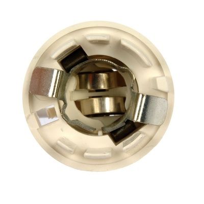
this is looking down into a tail light socket with both tail and turn/stop circuits..

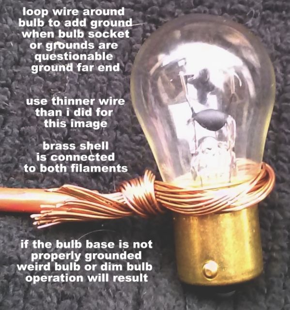
note that the  circular shell holds and actually grounds the bulb.. but.. its grounded only thru the tail light housing.. if its not secure.. or the tail light housing is poorly grounded. you will have issues.. drop to the bottom of this first section for a fix that can be for testing.. temporary or forever..


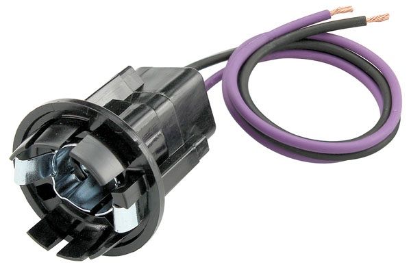
this is a side view.. so you get a better idea of what you are looking at..


the white colored version.. this is a mid to late 60s gm tail light socket..  that there is a hole at the 8 o clock position..

a similar opening on the black version at the same 8 o clock position.. more on that later..

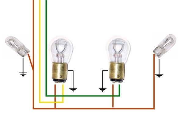
lets look at standardized mid 60 to mid 70s tail light and side marker light wiring..

note that the stop/tail light bulbs are grounded by the shell..  the side marker lights are individually grounded .


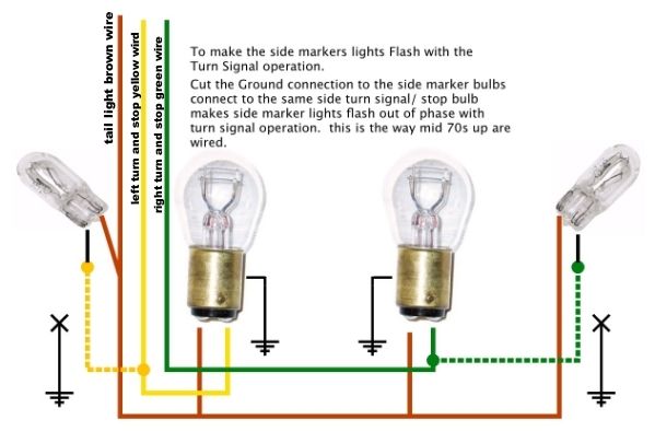
this is how mid 70s thru late 90s  tail lights are wired..

less my splices..


converting the side marker light wiring to this set up makes the side marker lights flash out of phase.. with the turn signals... and still maintain the bulbs showing when the tail lights are on without the turn signal lights flashing..

so.. back to the original title..

tail lights go out when you step on the brakes or operate the turn signals...

strip back several inches of 16 or 18 gauge wire.. loop it around and reinsert the bulb into the socket.. then feed the new ground wire thru the hole at 8 o clock as shown way above..  once the bulb and socket are back in the housing.. put a ring terminal on the end of the new ground wire and attach it someplace that is a good ground to supply electrons from the negative side..

#25
Rodder's Roundtable / LS7 chevy engine article..
May 22, 2013, 09:33:15 PM
ran across this well written LS7 chevy article.. thought i would share..

http://www.camarohomepage.com/ls7/index.htm
#26
Rodder's Roundtable / Full National radar loop
May 21, 2013, 01:59:20 PM
this is the FULL national radar loop.

there are regional loops  down below


http://radar.weather.gov/Conus/full_loop.php


this should probably be moved after the storms have passed or a bunch of people have bookmarked the link.. to the tech section

hope everybody is going to be ok..
#27
a question for the members

is there a filler material to fill carved out pot holes in sheet metal that was chromed...  but has been stripped and is needing to be rechromed but the road rash of pot holes is hindering the process..

something that could be applied with a TIG welder??? or a micro torch.. or even to surface the entire material.. like you would tin something with solder..

that would allow one to smooth the entire surface again..

i know that brazing rod will not work..

but i recall that there were other types of bronze rod..

aluminum bronze.. or silicone bronze..

my thoughts are on chromed stamped sheet metal chevy grills from the late 40s..  but this could be used on later steel parts also..  i know that new ones are usually available..
#28
http://www.autospeed.com/cms/A_111110/article.html?popularArticle


read linked article above before reading my thoughts below.

this might be a great use for those gopro cameras or mounting a quality cell phone camera or small high def video camera on a bracket off to the rear or side of the car..  something tubular and out of the air stream..

and finding some place to get the car up to speeds..


i thought up a hollow spoiler for the rear deck that the upper surface mounts to the horizontal deck surface and the rear layer mounts to the vertical surface.. with vertical bracing inside.. openings along the gap to allow air to be pulled out the back of the car..  an adjustable rear side panel... so you could adjust the amount of siphon effect on the top edge of the spoiler by the air flow..


and since i am blowing in the wind on this one..

a few of you are aware that Most OBD2 cars have 3 wire fuel tank pressure sensors that are very accurate and sensitive in both positive and negative inches of water column..  i don't know what the total range is.. but that would be easy to figure out..   some techs have rigged these to an extra radiator cap adaptor and a 9 volt battery .. wiring to their very expensive digital storage occilloscopes.. to look for combustion leaks in cooling systems by looking at the tiny pressure changes in the cooling  while cranking or idling with the water pump not spinning.. .  yep.. sensitive..  these could be used to monitor the pressure above the rear of the car... and below the car... to see/warn the driver if the pressure below the car becomes greater than the pressure above the car..  indicating the car is about to lift at speed..

one wonders if extending the rear of the front wheel wells downward with something like a mud flap off a truck.. but positioned at an angle.. kicking more air out from under the car.. in the middle of the car..  in addition to the front air dam.
#29
just ran across this site for a TR6..

but it should work for any car...


http://tr6.danielsonfamily.org/FenderBlanket.htm

be sure to look check out the pockets ..

one could mark a cheep moving blanket with a chalk or sharpie and hand it to an upholstery shop to have them stitch it up for you..

use some Newspaper, masking paper or butcher paper to design the flaps inside the fenders... then cut it out and  transfer the pattern to  to the blanket.

most upholstery shops also have sheets of what most call AIR FOAM.. its like 24 inches by 60 inches one inch or an inch and a half thick... those could be sewn onto the bottom or stitched inside to protect the fender tops even better..

as long as no body lays these on the floor.. and checks them carefully before installation.. it might not scratch the paint..


i was always thinking of the light blue plastic window film that contractors stick over existing windows to prevent the need for overspray cleanup and scratches..  this might work on the fender tops also..
#30
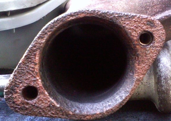
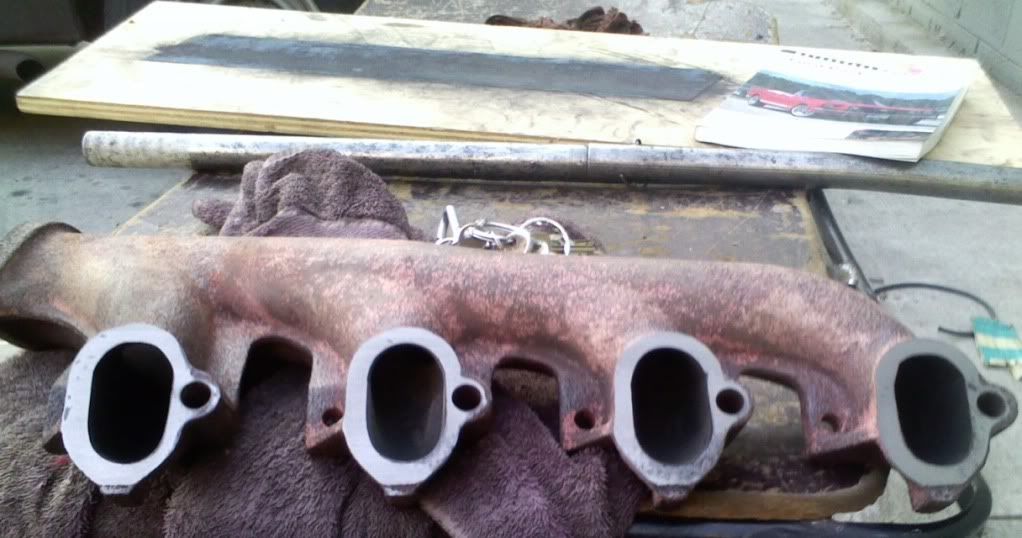
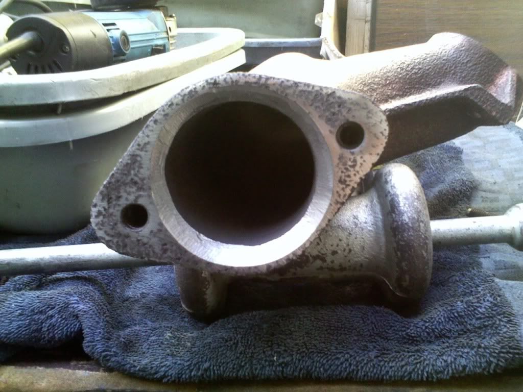
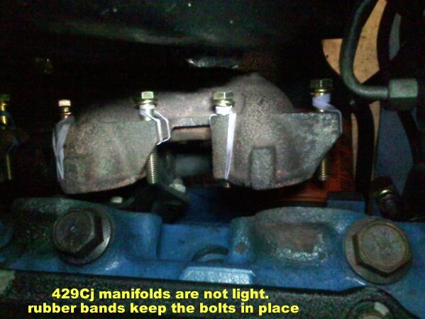
i thought i would share some images from a 429CJ  i repaired the exhaust leaks on last week...


one can see the blue belt sander paper i glued to a piece of 3/4" plywood.. if i had thought about it earlier i would have screwed some 2x4s to the back and verified it was flat with a straight edge.. as it was.. the weight of the manifold required me to prop the center up on the towel to really get the center 2 ports.... it also took 3 of us to support the off center weight of the manifold and 2 to push down on the back then back and forth to get through the crud...  the other manifold was worst but i forgot to take pictures..


the flat surface i hit with my 4" angle grinder with a flap disc... just because it was so ugly..

the angled surface i worked with my 1/4" electric die grinder with a 1/2" tree shaped carbide tool.. i have a tons of experience with that tool messing around in ports and other locations.

i test fit the exhaust flange rings... what's strange is i was able to use a  felpro 60201 exhaust flange ring on one manifold and the stepped version 60218 on the other.. that was because of who ever created the exhaust pipes... not the manifolds..


to avoid aggravation while trying to get the exhaust manifolds in... i broke out the rubber bands..


OH... and on the 429CJ and 429SCJ motors... standard exhaust gaskets won't fit.. the port openings are too short.. you have to use the fel pro performance 1420 or even the 1421 but those are shown with ported heads...

for those who spotted it.. one of the flange holes is heli coiled..

i used the dorman #03135 for the exhaust flange studs    7/16 -14 studs with the hex and it worked out fine.. it came with 11/16 hex size brass nuts...
#32
just curious if a stubby 4L60 or 700R4 could be created using a 4x4 case. creating a backing plate like is used on stubby powerglides...

so people with the need for short transmissions could use the overdrive transmission

i know this is a real nitch market..  but i know there are several members here that might have already done it..
#33


this is better than my idea to put small speakers in bird houses to teach baby birds the star spangled banner,  dixie.. la cocaracha..
#34
hacker alert... Windows does NOT call you at home or at work warning that you have a virus in your computer.

one just called me from 206 397 1127

i managed to keep him on the line wasting his time for almost 10 minutes...

his script started like this..

hi.. this is windows calling...  your microsoft computer has a serious virus in it.. to remove the virus please depress the windows key and the R key...   it will open a small window.. type in this number...

i kept him going..  even restarting my machine... holding the phone to the macintosh speaker so he could hear the start up gong..  but he could not hear it..   oh..i neglected to tell him that i had a mac...

i tried to keep him on the phone longer but he got ugly and hung up...  i was going to tell him that the predator was only 3 minutes from being in range... and that i needed him to stay on the line to verify we got the right target by listening for the explosion...

please alert your family members that windows DOES NOT CALL YOU  if you have a virus...

i know this is the wrong forum to place this.. i am sure it will get moved to the throne room in a few days..  its just to protect the forum members...
#35
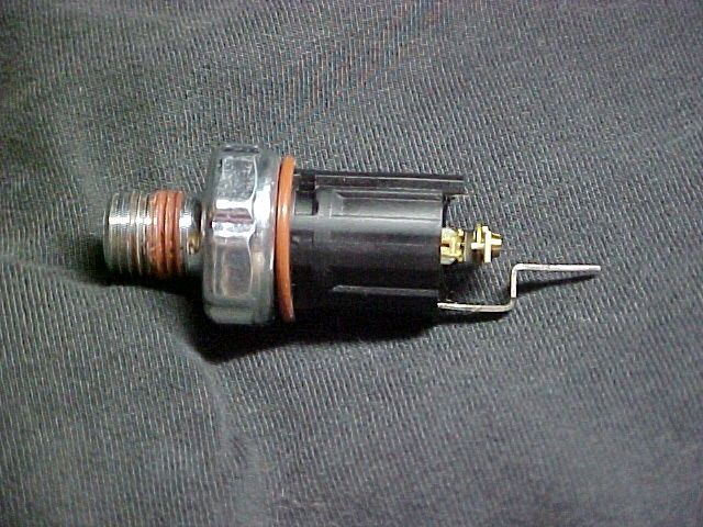
i have found that an important test for GM electric fuel pumps has been skipped somehow..

engine idling...  pull the fuel pump relay or remove the wiring connector from it....  the engine SHOULD continue to idle.. and run as normal.

if the engine dies..  change the oil pressure switch..

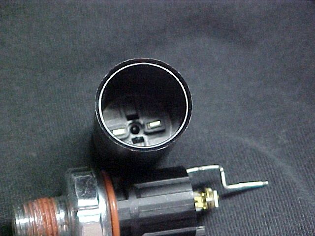
look at this first diagram.. just the upper half..


see the orange wire.. that sends power to the fuel pump relay.. but also to the fuel pump control terminals on the oil pressure switch..  see those below..

the OIL pressure switch should be handing most of the current for the fuel pump circuit.. not the tiny pins of the relay..

this redundant circuit is to make sure that you get where you are going without stalling out..

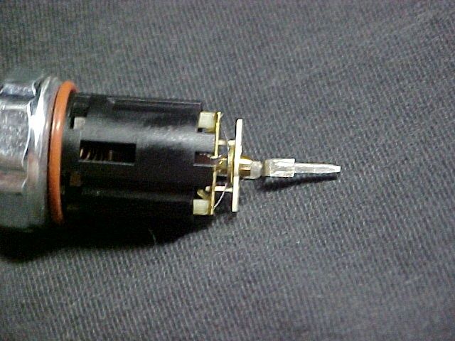
can you see the bent lead in this image.. that is for the oil pressure switch. for the gauge circuit.  its the BAR and the outer 2 contacts in the cap that we are worried about..


when the oil pressure comes up slightly. probably 6 or 7 psi.. the BAR is pushed against the terminals inside the socket..  creating a complete circuit to power the fuel pump.. the problem is..  its NOT a wiping contact..  the spots where it touches are the same each time..  so it can build up corrosion and oxides to prevent proper contact.. when this happens...   all the current for the fuel pump supply circuit will be sent through the fuel pump relay...

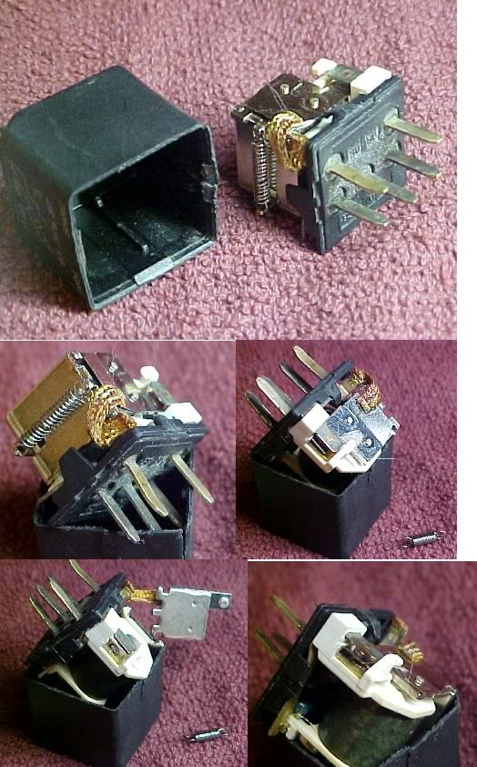
this is what a lot of gm cars and trucks use for a fuel pump relay..  some have larger terminals.. some a micro sized case.. theory is the same..


the contacts get dirty..  

when the oil pressure switch fails.. all the fuel pump current is sent through this side of the harness..  look at the size of the pins.. they are tiny.  the connectors in the socket get loose from thermal cycling.. then you burn up relays..  leaving you stranded sometimes.  or odd stalling issues.. where the engine will just quit..  and then restart..

in the diagram above..  you will see the dark green and white striped wire  to the coil windings of the fuel pump relay..  the computer on most GMs.. sends positive voltage to the fuel pump relay coils to activate the relay.. which is reversed from almost everything else controlled by the computer..  please be VERY careful in diagnosing the green and white striped wire.. if your test light pulls more than one amp...  you can burn the power transistor out inside the computer.. creating an unseen problem that will drive you crazy..

you will also see that one of the wires runs to the ALDL connector.. thats the fuel pump prime circuit.. i don't know if all the GM cars with ALDL connectors and electric fuel pumps are equipped with that.. most of the tuned port injected cars are with OBD1 connectors..

there is another source of power for the fuel pump.. thats really not well known.. its shown on the diagram close to the bottom of the upper section..  thats the HOT fuel module..

that is mounted under the hood someplace..  it keeps the fuel pump running when the engine is shut off and fairly hot.. to cool the injectors from heat soak from the engine..  also stops the fuel from boiling in the fuel lines from the heat when shut off..  its hard to tell which cars are equipped with it..  this diagram is for the 7747 ECM used on a lot of gm port fuel injected cars.. and a lot of PFI and TPI swaps..

i hope that this tidbit of info and 5 minutes of reading time save you some headaches by finding an invisible issue before it happens...

one thing..  if you look at the threads of the oil pressure switch above..  they are WRONG... who ever rolled those threads rolled them to 1/2-13 UNC... not 1/4-18 NPTm  it's close.. it will thread in.. but it will also send off big turnings of steel when installing it into the STEEL adaptors that GM has on their engines..  so feel the threads on any oil pressure switch you buy..  if they are NOT smaller in diameter slightly at the first and larger at the top of the threads.. don't buy it..  i know there might be an application for the 1/2-13 straight thread.. but somebody screwed up with this one..

#36
sorry... this is kinda off subject..  

but i ran across this and with diesel prices going through the roof.. this might be an option..


http://www.omnitekcorp.com/altfuel.htm

it does require a tear down and mods...

so its NOT an easy conversion..


but knowing about it might help someone..
#37
http://boingboing.net/2012/02/13/machines.html


a link from the above article...

http://www.archive.org/stream/plantproductofme00mest#page/n135/mode/2up


i thought that all of you might really enjoy these massive machines...

this is not a quick read.... enjoy

wayne...  finder of the obscure
#38
i was just drifting around the web... ran across this...

this is the best bearing selection catalog i have run across....

http://www.kml-bearing.com/products/bearings/automotive_bearings.jsp


search around in there..

i found specs on stuff that i did not know was available...
#40
just saw this in a magazine that i would imagine that few rodders read..


http://www.4wdandsportutility.com/tech/1202_4wd_swag_off_road_hydraulic_tubing_bender_conversion_kit/index.html

thought it might help a few rodders..


although... i would personally add a LONG U shaped piece to lock the clamp on the upper cylinder.. to the base plate to avoid just blowing the cylinder off the base...  as i don't think its really designed for that kind or pressure  ...   action / reaction sort of effect..
#41
Rodder's Roundtable / detailed flat head V8 build..
December 17, 2011, 02:17:45 AM
and one more.. a detailed article on building a Flat head ford V8

i know that some of you get these in print.. but not everybody does..

http://www.rodandcustommagazine.com/techarticles/1112rc_crash_course_on_flatheads/index.html
#42
Rodder's Roundtable / 1949 Cadillac Sedanet from HRM
December 17, 2011, 12:45:42 AM
its been kinda slow here.. though  i would speed it up with a luxo ride in a caddy..

enjoy..


http://www.hotrod.com/featuredvehicles/hrdp_1112_1949_cadillac_sedanet/
#43
Rodder's Roundtable / X mas shopping for the Hotrodder..
November 30, 2011, 10:04:20 AM
this is better than the sears christmas catalog..

or Even the craftsman tool catalog..  about equal with the snap on catalog..

http://www.circletrack.com/techarticles/ctrp_1201_roush_yates_parts_cup_level_components/index.html
#44
Rodder's Roundtable / clear Glass engine coolant tubes...
November 29, 2011, 12:22:17 PM
i just ran across this..  its in an obscure mag to most rodders...  thought it might interest some of you...

and please.. remember..  when pouring coolant into these..    Don't inhale.. :shock:


enjoy...

http://www.sporttruck.com/techarticles/0408st_engine_compartment_blown_glass_hoses/index.html


for a quick look at what is in the article ... click this picture link..

http://image.sporttruck.com/f/18345342+w750+st0/0408st_33_z+optiflo+radiator_fluid_in_glass.jpg
#46
i would like you to drag out your handy digital volt meter...

set it to 20 volts DC.... get the hood open...

get the car started... turn on the headlights.. . you should be able to do this in under 2 minutes...

copy and paste this and print it out large,  paste it to a wall in the shop..

1. test between the positive and negative battery POSTS... 14.1 to 14.8 volts is expected...

2. test between the Negative battery POST and the engine block.. 0.04 volts is expected..

3. test between the Negative battery POST and the body .. 0.02 volts DC is expected..

4. test between the engine block and the body... 0.02 volts is expected..

if you get 0.00 on tests 2, 3, 4,... change the meter setting to 2 volts DC.. and do test 2, 3, and 4 again... looking for the small voltages posted..

the 0.04 and 0.02 voltages are correct for ground to ground with the engine running and the headlights on..

if you get much more than the tiny readings.. you have a bad ground... and that needs to be fixed first...


this test can be done in under 2 minutes... has to be done with the engine running.. and the headlights on...

will find all kinds of gremlins that will trip you up....

remember... electrons flow from Negative to positive... if you have a bad ground between parts.. you may not have enough electrons to do the job... if you have a bad ground... when the alternator is charging.. there might be way too many electrons trapped on the engine... causing weird voltage problems.... like you are having..

this is really the first test i do on EVERY CAR that comes in.. and usually i do it before it leaves just to verify...
#47
I saw this over in HRM... figured that she made a big enough impact to post it here..


the whole article
http://www.hotrod.com/thehistoryof/hrdp_1107_linda_vaughn/viewall.html


the start of the pictures and captions... 39 photos

http://www.hotrod.com/thehistoryof/hrdp_1107_linda_vaughn/photo_01.html


i got to see linda up close a few times over the years .. got to meet some of the people featured in the article...

roland... snake,   keith black,   * landy,  i know a lot of you did also..
#48
just ran across this...

http://www.streetrodderweb.com/tech/1048srp_ford_flathead_intake_manifold_collection/index.html

each picture will open in a new window...  easy to save..   it has how become my flat head screen saver...
#49
sorry.. this was too good to drop into the waters of the throne room...


http://www.trucktrend.com/features/travel/163_news110701_nau_camper_concept/index.html


be sure to look at the individual images...

this design could be worked with.. into a beautiful trailer...

perhaps i am far sighted... or far fetched... but i think it might work...
#50
yea.. not really a rodding subject.. but over the last few years i noticed that the in car temps were getting higher and higher...

then i see a bell helmet... with scoops on the front and vents on the back

would not on hot days... be a good idea to stick a few layers cut into a small section of 200 mile an hour tape under the center of one of the roof flaps to allow a siphon effect of the hot air from inside the drivers compartment  without ruining the aerodynamic effects of the car...


perhaps... even getting stant or one of the thermostat companies to create some lower temp thermostat devices... that push a vent open when the interior temps raise above 115 or 120F.... this could be used on other applications also...  

this is just an idea.. but since there most of the nascar racing takes place elsewhere.. i never make it to the circle track events..

i figure that at least some of you know a racer...  where the idea could be passed along...

even though i share a last name with the king.. its probably just a name.. i found that my branch of petty's arrived around 1640 to what was to become richmond county va.